Categories
Embedded Networking

Trials and Tribulations of using Embedded TCP

I was recently called in for a consult on a program that was having trouble with their 802.11 link.

The team working on this program had created a system using a number of embedded micros which were to communicate via Ethernet on an embedded LAN. In my experience, network communications on an embedded LAN normally run fairly smoothly because you are in total control of the environment. You can design the system based on the bandwidth required and put in Ethernet controllers which support those bandwidth requirements.  You can control who talks when and totally avoid the possibility of collisions occurring.

As it turns out that the system created was so complex that the team was unable to get all these micros communicating effectively in a timely fashion while at the same time doing all the number crunching that needed to be done.  The decision was made to backtrack a bit and prototype some of the systems on PCs instead of micros.

This course of action lead to the use of the 802.11 link; what was to be an embedded LAN now became partially embedded and partially a wireless LAN connecting the PCs.  Wireless LANs have their own issues–link saturation, SNR, etc.–some of which I’d had to deal with in the past on prior projects. This is what prompted the request for my help; the team was getting very little data across their wireless link and couldn’t understand why.

After asking a few questions I discovered a couple things:

  1. they were using TCP/IP for their network connections, and
  2. the software engineers had never done network programming

These two factors, combined with the wireless LAN, made for the perfect storm.

The low bandwidth that the team was seeing was due to the fact that TCP uses an exponential backoff mechanism when attempting to guarantee packet delivery. What caused the backoff to occur in the first place were some easily fixed wireless hardware issues.

What compounded the issue was the fact the the socket code on the micros was sending data without regard for the health and status of the socket.  In essence, they were also overflowing their transmit buffers.  This was because the engineers writing the code didn’t know any better.

After shaking my head and rolling my eyes at the state of affairs, the issues were fixed by resolving the wireless hardware issues and instructing the engineers in the use of the select() function to control the flow of data on the socket and monitor its health.

The system now works and the team recently executed a very successful demonstration, but I still have an issue with the fact they are using TCP in the system. Since you control the network and all the traffic on an embedded LAN, TCP is not required.  TCP is designed for traveling long distances through hardware of unknown origin and state; it is not required in a highly controlled embedded environment. In this environment, for this program, UDP is more than sufficient. Here’s why:

  1. The system is tolerant to a small percentage of data loss.
  2. UDP packets are checksummed at higher level–Ethernet CRC checksum and IP Header checksum.  If you get a packet then you are pretty much guaranteed the data is correct.
  3. The 100Mbps links on the system above provides more than ten times the bandwidth required–it had 5 nodes each transmitting less than 1 Mbps.  Staggering their communications to avoid collisions is a simple matter.
  4. Fragmentation can be eliminated by sending data in blocks no larger than a single MSU.
  5. UDP simplifies.  Creating and maintaining connections of a TCP socket can be time consuming and distracting, adding a lot of code with no added value.
  6. UDP datagram loss on a closed embedded LAN is negligible.

Item 5 and 6 above were particularly costly in this instance, many hours were spent maintaining connection oriented code when the occasional loss of data would not have had a negative impact on the system results.  In this case, even including the wireless LAN, iperf tests showed less than 0.02% datagram loss at the bandwidths this system was running.

Just as everything else posted here, this is one engineer’s opinion.  I hope by stating it, I can help you avoid some of the travails I’ve experienced.
Categories
Embedded

Reading BeagleBoard User Button (or any GPIO)

This one is short and sweet, based on the blinking LED example found here.

Here’s a shell script to read a GPIO and generate a square wave on the console:

#!/bin/sh
#
# Read a GPIO input

GPIO=$1

cleanup() { # Release the GPIO port
  echo $GPIO > /sys/class/gpio/unexport
  echo ""
  echo ""
  exit
}

# Open the GPIO port
#
echo "$GPIO" > /sys/class/gpio/export
echo "in" > /sys/class/gpio/gpio${GPIO}/direction

trap cleanup SIGINT # call cleanup on Ctrl-C

THIS_VALUE=`cat /sys/class/gpio/gpio${GPIO}/value`
LAST_VALUE=$THIS_VALUE
NEWLINE=0

# Read forever

while [ "1" = "1" ]; do
  # next three lines detect state transition
  if [ "$THIS_VALUE" != "$LAST_VALUE" ]; then
    EV="|"
  else
    EV=""
  fi

  # "^" for high, '_' for low
  if [ "1" = "$THIS_VALUE" ]; then
    EV="${EV}^"
  else
    EV="${EV}_"
  fi
  echo -n $EV

  # sleep for a while
  sleep 0.05

  # wrap line every 72 samples
  LAST_VALUE=$THIS_VALUE
  THIS_VALUE=`cat /sys/class/gpio/gpio${GPIO}/value`
  NEWLINE=`expr $NEWLINE + 1`
  if [ "$NEWLINE" = "72" ]; then
    echo ""
    NEWLINE=0
  fi

done

cleanup # call the cleanup routine

I saved this as ~/read_gpio, did a ‘chmod 755 read_gpio’and invoked it to read the user button, GPIO 7:

root@beagleboard:~# ./read_gpio 7
_________________________________|^^^^|_____|^^^|_____________|^^^|___|^^^|_____
____|^^|____|^^|____|^|________|^^^|_______|^^|____________|^^^|______|^^|_______

root@beagleboard:~#

Sampling at a 50ms interval appeared to catch most of my button pushes, even at an unreasonably high rate. A 100ms interval was too long and some of the faster button pushes were missed.

Categories
Embedded

BeagleBoard as USB Mass Storage Device via USB OTG

The first thing to do is enable the file storage gadget module in the kernel as such:

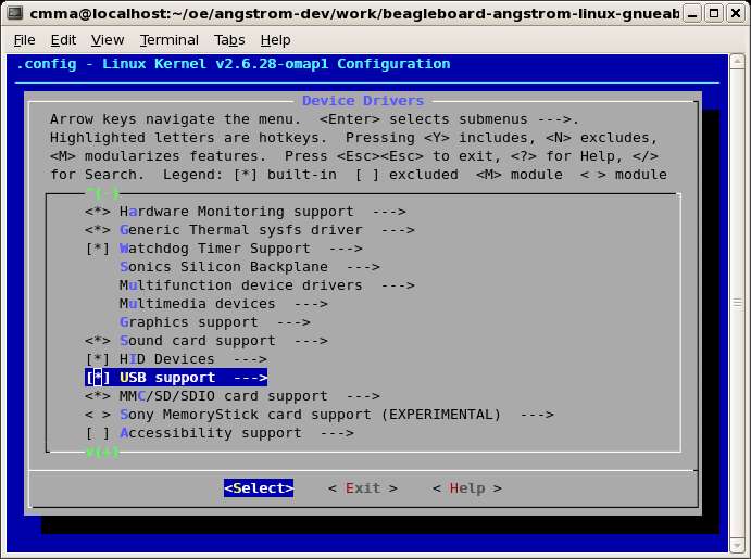
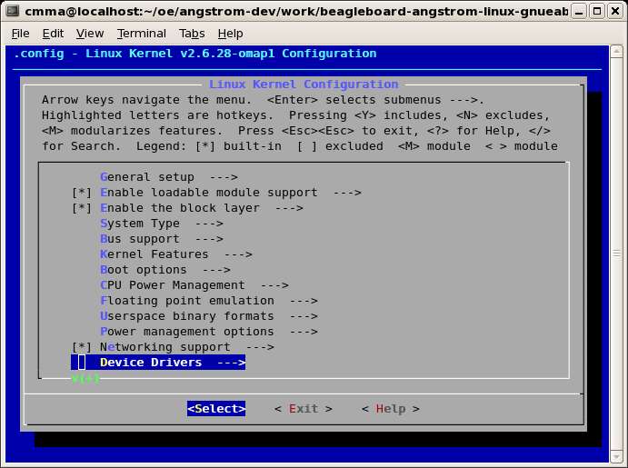
Device Drivers

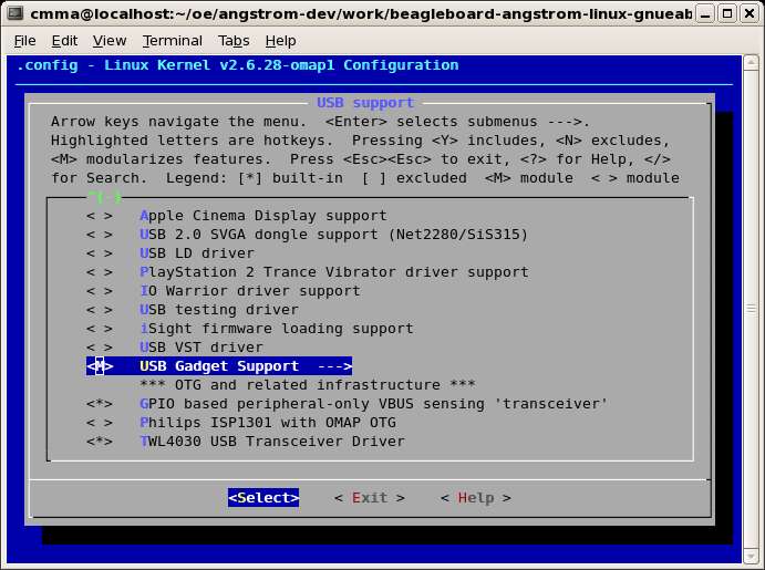
USB Support (*)

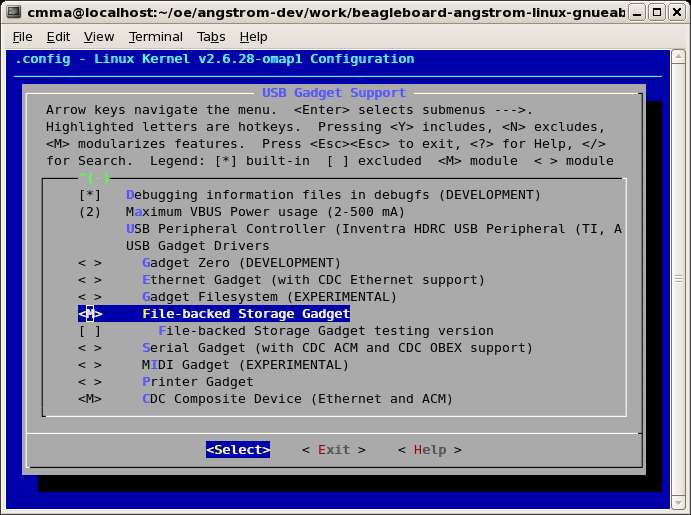
USB Gadget Support (M)

File-backed Storage Gadget (M) | CDC Composite Device (Ethernet and ACM) (M)

Exit all the way out and save your changes. Rebuild the kernel by following the steps in this previous post.

I had to add a few packages to the root file system in order for the BeagleBoard to have all the tools on board to configure the backing storage for the file storage gadget.  These packages were ‘dosfstools’ and ‘parted’ and they were added to my image recipe, cmma-ptrp-image.bb:

# added for file backed storage support for file storage gadget
ANGSTROM_EXTRA_INSTALL += " dosfstools parted "

I was able to automate the process for creating the backing storage.  The script below creates and mounts a 64MB backing store and can be copied onto the SD card in the root file system and executed from the BeagleBoard command line:

#!/bin/sh
if [ "${#}" != "1" ]; then
  echo "usage: $0 "
  exit 1
fi 

/bin/dd bs=1M count=64 if=/dev/zero of=${1}
if [ "$?" != "0" ]; then
  echo "Failed to create block file $1"
  exit 2
fi

/usr/sbin/parted ${1} mklabel msdos
if [ "$?" != "0" ]; then
  echo "Failed to create partition label on $1"
  exit 3
fi

/usr/sbin/parted ${1} mkpartfs primary fat32 0 64
if [ "$?" != "0" ]; then
  echo "Failed to create partition on $1"
  exit 4
fi

NSTART=`/sbin/fdisk -lu ${1} | /usr/bin/awk '/FAT32/ { print $2*512 }'`
if [ "$?" != "0" ]; then
  echo "Failed to set NSTART"
  exit 5
fi

/sbin/losetup -o ${NSTART} /dev/loop0 ${1}
if [ "$?" != "0" ]; then
  echo "Failed to create loopback for $1"
  exit 6
fi

/usr/sbin/mkdosfs /dev/loop0
if [ "$?" != "0" ]; then
  echo "Failed to make dos fs for file $1"
  exit 7
fi

MTPT=`pwd`/loopback
/bin/mkdir -p ${MTPT}
if [ "$?" != "0" ]; then
  echo "Failed to create mount point ${MTPT}"
  exit 8
fi

/bin/mount -t vfat /dev/loop0 ${MTPT}
if [ "$?" != "0" ]; then
  echo "Failed to mount $1 on ${MTPT}"
  exit 9
fi

echo "Created ${1} and mounted on ${MTPT}"
echo ""
echo "To unmount:"
echo "  umount /dev/loop0"
echo "  losetup -d /dev/loop0"

This will allow the BeagleBoard to manipulate the data in the backing store as a local file system mounted on ${MTPT}.  In my BeagleBoard-based device this will be one mode of operation.

To test this functionality I setup the backing storage file (‘fsbackfile’) and mounted it with the script above (saved as ‘mkbackfile’) then copied some files to it:

$ ./mkbackfile ./fsbackfile
64+0 records in
64+0 records out
mkdosfs 2.11 (12 Mar 2005)
Loop device does not match a floppy size, using default hd params
Created ./fsbackfile and mounted on /home/root/loopback

To unmount:
  umount /dev/loop0
  losetup -d /dev/loop0
$ cp /etc/services ./loopback
$ cp /etc/passwd ./loopback

On my device a button push will invoke the file storage gadget mode by unmounting the BeagleBoard local loopback file system and invoking the ‘modprobe’ command to load the File Storage Gadget module.  For testing purposes I did this by hand on the BeagleBoard:

$ umount /dev/loop0
$ losetup -d /dev/loop0
$ modprobe g_file_storage file=/home/root/fsbackfile

Now the BeagleBoard is ready to plug into a PC as a mass storage device.

To test the file storage gadget I connected the correct cable to the mini-USB port on the BeagleBoard and to the standard USB port on my Linux development box. My BeagleBoard automounted and I was presented with a fle manager window showing the contents of the device–two files, services and passwd. Success!!!

Just to make sure everything was functional, I then used gedit to edit the passwd file and save it back to the device. I then unplugged the USB cable on the Linux development machine side. On the BeagleBoard I remounted the loopback device:

$ /sbin/losetup -o 16384 /dev/loop0 /home/root/fsbackfile
$ mount /dev/loop0 /home/root/loopback
$ ls /home/root/loopback
services         passwd  ~passwd

We can see that the gedit backup file has been created. Looking at the contents of passwd and ~passwd revealed the expected contents.

This completes the successful demonstration of BeagleBoard as File Storage Gadget.

Categories
Embedded

In-place OE/Bitbake Kernel Modifications for BeagleBoard

As mentioned in a previous post, if you follow the recommendations for setting up and building OE,  the bitbake process cleans up after itself and you can not make in-place modifications to the kernel source.  Granted it is preferable to setup a local overlay in which to do all your work, but it you just want to make a quick change and test it, this process will save you a little time.

After setting up the OE environment (and building everything once to make sure your environment is configured correctly, see Building OpenEmbedded for BeagleBoard and Building Angstrom…) do the following:

$ cd ${OETREE}/build
$ bitbake -c clean linux-omap-2.6.28
$ bitbake -f -c compile linux-omap-2.6.28

The above commands will clean and build a fresh copy of the kernel, leaving the sources in place for future use; you can find them here:

$ cd ${OETREE}/angstrom-dev/work/beagleboard-angstrom-linux-gnueabi/linux-omap-2.6.28-r18/git
$ ls
COPYING        Makefile        arch      fs       lib            samples   virt
CREDITS        Module.symvers  block     include  mm             scripts   vmlinux
Documentation  README          crypto    init     modules.order  security  vmlinux.o
Kbuild         REPORTING-BUGS  drivers   ipc      net            sound
MAINTAINERS    System.map      firmware  kernel   patches        usr

From here you can reconfigure the kernel. After ensuring ncurses was installed:

$ yum install ncurses-devel

I was able to

$ make menuconfig

and make my modifications. After saving my configuration changes to update the .config file, it was a simple matter of rerunning the forced compile step from above to rebuild the kernel:

$ bitbake -f -c compile linux-omap-2.6.28
$ bitbake -f -c deploy linux-omap-2.6.28

If your kernel configuration modifications happen to result in the generation of any loadable modules, then you will wind up with another file in the deployment images folder:

$ cd ${OETREE}/angstrom-dev/deploy/glibc/images/beagleboard
$ ls mod*
modules-2.6.28-r18-beagleboard.tgz

This file will need to be copied to your SD card and extracted in-place after you’ve extracted the rootfs to the SD card. I use the following script (~/bin/mvrootfs) to accomplish this:

#!/bin/bash
if [ "$(id -u)" != "0" ]; then
  echo "This script must be run as root" 1>&2
  exit -1
fi
if [ "${#}" != "1" ]; then
  echo "usage: $0 sd[x]"
  exit -2
fi 

source /home/cmma/oe/source-me.txt

DV=/dev/${1}2
ROOTFS=cmma-ptrp-image-beagleboard.tar.bz2
MODULES=modules-2.6.28-r18-beagleboard.tgz
DEST=/media/LABEL2
DEPLOY=${OETREE}/angstrom-dev/deploy/glibc/images/beagleboard

/bin/cp -f ${DEPLOY}/${ROOTFS} ${DEST}
/bin/cp -f ${DEPLOY}/${MODULES} ${DEST}

cd ${DEST}
/bin/tar -jxvf ${ROOTFS} && rm -f ${ROOTFS}
/bin/tar -xvzf ${MODULES} && rm -f ${MODULES} 

cd
/bin/sync
/bin/umount /dev/${1}?

Where the name of my image is cmma-ptrp-image, OETREE=/home/cmma/oe and I am using an SD card configured according to these instructions. If my SD card mounts on /dev/sdb, I invoke the script as such:

$ sudo ~/bin/mvrootfs sdb

Then simply put the SD card back in the BeagleBoard and power up.

Categories
Embedded

Modifying and rebuilding u-boot

I highly recommend starting with a fresh OE/Angstrom install following these directions.

NOTE: This process is not as easy as it should be because the default ‘local.conf’ includes the line:

 INHERIT += " rm_work "

which removes the source after everything has been compiled and deployed–this leads to a lot of confusion when reading posts that say the source can be found in ‘tmp/work…’ or ‘angstrom-dev/work…’.  Having previously built images will also populate your folders with a lot of stuff that is extraneous, and that’s why I recommend a fresh install.

Also, I did port over my local overlay as described here, adding ‘${OETREE}/local/recipes/*/*.bb’ to the BBFILES assigment in the ‘local.conf’ file.  I did this to include my app, not to update u-boot.  I did this before invoking any bitbake commands in the links mentioned above.

I then performed a bitbake of my own image, from my local overlay (which builds on console-image) with:

$ bitbake cmma-ptrp-image

(This could have just as easily been:

$ bitbake console-image

for a default install without a local overlay.)

This ran for a few hours and completed successfully.  Since I was then unable to find the u-boot source code  under ‘${OTREE}/angstrom-dev/work…’ (I suspect due to the default use of the rm_work task) I ran the following:

$ source ${OETREE}/source-me.txt
$ bitbake -f -c clean -b ../recipes/u-boot/u-boot_git.bb
$ bitbake -f -c compile -b ../recipes/u-boot/u-boot_git.bb

which forces a recompile of u-boot, leaving the source in place.  I then found the source in:

${OETREE}/angstrom-dev/work/beagleboard-angstrom-linux-gnueabi/u-boot-2008.10+r22+gitrb7038cff739684bb95853eb5bee924c2574a222e-r22/git

After applying my pin mux modifications in board/omap3/beagle/beagle.c (see the bottom of this post) I ran the following:

$ bitbake -f -c compile -b ../recipes/u-boot/u-boot_git.bb
$ bitbake -f -c deploy -b ../recipes/u-boot/u-boot_git.bb

I was then able to copy ‘u-boot-beagleboard.bin’ in ‘${OETREE}/angstrom-dev/deploy/glibc/images/beagleboard’ to my SD card.

After rebooting the beagleboard and logging in, the command:

$ cat /etc/services > /dev/ttyS0

results in a wiggly line on the scope connected to pin 15 of J5 on the beagleboard, the UART1_TX line.

Categories
Embedded

Enabling UART1 on Rev C2 BeagleBoard

I am updating this post to put the preferred method up front–that is modifying u-boot.

And I’ve expanded it to include:

  • UART1 (/dev/ttyS0) Rx/Tx/CTS/RTS on J5
  • UART2 (/dev/ttyS1) Rx/Tx on J3
  • Other GPIOs as needed

The pin mux can be reconfigured in u-boot (thanks, Antti.)

To do this we edit board/omap3/beagle/beagle.c (changes in bold):

/******************************************************************************
* Routine: set_muxconf_regs
* Description: Setting up the configuration Mux registers specific to the
*        hardware. Many pins need to be moved from protect to primary
*        mode.
*****************************************************************************/
void set_muxconf_regs(void)
{
    MUX_BEAGLE();

    if(beagle_revision_c) {
        MUX_BEAGLE_C();
    }

	/* reset default beagleboard UART configs to avoid conflicts */
    MUX_VAL(CP(UART1_TX),        (IDIS | PTD | DIS | M7)) /*UART1_TX*/
    MUX_VAL(CP(UART1_RX),        (IDIS | PTD | DIS | M7)) /*UART1_RX*/
    MUX_VAL(CP(UART2_RX),        (IDIS | PTD | DIS | M7)) /*UART2_RX*/

    /* reset DSS_DATA[0,1,6,7] lines to UART1 mode */
    MUX_VAL(CP(DSS_DATA0),       (IEN  | PTU | EN  | M2)) /*UART1_CTS*/
    MUX_VAL(CP(DSS_DATA1),       (IDIS | PTD | DIS | M2)) /*UART1_RTS*/
    MUX_VAL(CP(DSS_DATA6),       (IDIS | PTD | DIS | M2)) /*UART1_TX*/
    MUX_VAL(CP(DSS_DATA7),       (IEN  | PTD | EN  | M2)) /*UART1_RX*/

	/* set UART2 lines */
    MUX_VAL(CP(UART2_TX),	     (IDIS | PTD | DIS | M0)) /*UART2_TX*/
    MUX_VAL(CP(MCBSP3_FSX),      (IEN  | PTD | EN  | M1)) /*UART2_RX*/

	/* setup GPIOs */

	/* our (not BB) push buttons */
    MUX_VAL(CP(I2C2_SDA),        (IEN  | PTD | EN  | M4)) /*GPIO_183*/
    MUX_VAL(CP(I2C2_SCL),        (IEN  | PTD | EN  | M4)) /*GPIO_168*/

    /* RYG LEDs */
    MUX_VAL(CP(MMC2_DAT7),       (IDIS | PTD | EN  | M4)) /*GPIO_139*/
    MUX_VAL(CP(DSS_DATA17),      (IDIS | PTD | EN  | M4)) /*GPIO_87*/
    MUX_VAL(CP(MMC2_DAT6),       (IDIS | PTD | EN  | M4)) /*GPIO_138*/

	/* 7-SEGMENT LEDs */
    MUX_VAL(CP(MMC2_DAT5),       (IDIS | PTD | EN  | M4)) /*GPIO_137*/
    MUX_VAL(CP(MMC2_DAT4),       (IDIS | PTD | EN  | M4)) /*GPIO_136*/
    MUX_VAL(CP(DSS_DATA15),      (IDIS | PTD | EN  | M4)) /*GPIO_85*/
    MUX_VAL(CP(MMC2_DAT3),       (IDIS | PTD | EN  | M4)) /*GPIO_135*/
    MUX_VAL(CP(MCBSP1_DX),       (IDIS | PTD | EN  | M4)) /*GPIO_158*/
    MUX_VAL(CP(MMC2_DAT2),       (IDIS | PTD | EN  | M4)) /*GPIO_134*/
    MUX_VAL(CP(MCBSP1_CLKX),     (IDIS | PTD | EN  | M4)) /*GPIO_162*/

    MUX_VAL(CP(MMC2_DAT1),       (IDIS | PTD | EN  | M4)) /*GPIO_133*/
    MUX_VAL(CP(MCBSP_CLKS),      (IDIS | PTD | EN  | M4)) /*GPIO_161*/
    MUX_VAL(CP(MMC2_DAT0),       (IDIS | PTD | EN  | M4)) /*GPIO_132*/
    MUX_VAL(CP(MCBSP1_DR),       (IDIS | PTD | EN  | M4)) /*GPIO_159*/
    MUX_VAL(CP(MMC2_CMD),        (IDIS | PTD | EN  | M4)) /*GPIO_131*/
    MUX_VAL(CP(MCBSP1_CLKR),     (IDIS | PTD | EN  | M4)) /*GPIO_156*/
    MUX_VAL(CP(MMC2_CLK),        (IDIS | PTD | EN  | M4)) /*GPIO_130*/

	/* EXTERNAL RESET */
    MUX_VAL(CP(DSS_DATA20),      (IDIS | PTD | EN  | M4)) /*GPIO_90*/

    /* misc */
    MUX_VAL(CP(DSS_DATA8),       (IDIS | PTD | EN  | M4)) /*GPIO_78*/
    MUX_VAL(CP(DSS_DATA9),       (IDIS | PTD | EN  | M4)) /*GPIO_79*/

}

Then rebuild u-boot. (That’s the separate story…)

Alternate Kernel Configuration

Here are the kernel file changes made to support use of UART1 on J4 and J5 connectors of the Rev C2 BeagleBoard.  This is based on pp. 817 and 899 of OMAP3 SCM (which just happens to use UART1 as an example of reconfiguring the pin mux settings) and this reference at HY Research.

File arch/arm/mach-omap2/board-omap3beagle.c:

Added function:

static void __init beagle_uart1_init(void)
{
    omap_cfg_reg(AG22_3430_UART1_CTS_UP);
    omap_cfg_reg(AH22_3430_UART1_RTS);
    omap_cfg_reg(F28_3430_UART1_RX_DOWN);
    omap_cfg_reg(E26_3430_UART1_TX);
}

At end of the function

static void __init omap3_beagle_init(void)

comment out the line:

/*beagle_display_init();*/

since we are remapping some of the DSS data lines to use the UART instead, then add the line:

beagle_uart1_init();

File arch/arm/plat-omap/include/mach/mux.h:

Additions to enum omap34xx_index shown in bold:

    /*  UART1 for BeagleBoard on J4/J5
     */
	AG22_3430_UART1_CTS_UP,
	AH22_3430_UART1_RTS,
	E26_3430_UART1_TX,
	F28_3430_UART1_RX_DOWN
}

File arch/arm/mach-omap2/mux.c:

Additions to the end of static struct pin_config __initdata_or_module omap34xx_pins[] shown in bold:

MUX_CFG_34XX("AE5_34XX_GPIO143", 0x172,
		OMAP34XX_MUX_MODE4 | OMAP34XX_PIN_OUTPUT)

/* UART1 for BeagleBoard on J4/J5
 */
MUX_CFG_34XX("AG22_3430_UART1_CTS_UP", 0x0DC,
		OMAP34XX_MUX_MODE2 | OMAP34XX_PIN_INPUT_PULLUP)
MUX_CFG_34XX("AH22_3430_UART1_RTS", 0x0DE,
		OMAP34XX_MUX_MODE2 | OMAP34XX_PIN_OUTPUT)
MUX_CFG_34XX("E26_3430_UART1_TX", 0x0E8,
		OMAP34XX_MUX_MODE2 | OMAP34XX_PIN_OUTPUT)
MUX_CFG_34XX("F28_3430_UART1_RX_DOWN", 0x0EA,
		OMAP34XX_MUX_MODE2 | OMAP34XX_PIN_INPUT_PULLDOWN)
};

Then rebuild the kernel (???)  To do this I need to understand where to apply the above changes.

(Turns out kernel mods are more complicated and everything I need can be done with simpler modifications to U-Boot.)

Categories
Embedded

Adding a Local Recipe to Angstrom/BeagleBoard

Here’s the directory structure I’ve created for a local overlay, with the name of my application being ptrp:

$ cd ${OETREE}
$ find local -type d
local
local/recipes
local/recipes/ptrp
local/recipes/ptrp/files
local/recipes/images
local/conf

The following changes were made to configuration files mentioned in previous posts (Building OpenEmbedded for BeagleBoard and Building Angstrom…) to support the new local overlay functionality:

~/.bashrc:

export BBPATH="${OETREE}/local:${OETREE}/build:${OETREE}/openembedded:"$BBPATH

(added ${OETREE}/local to BBPATH)

${OETREE}/build/conf/local.conf:

BBFILES += "${OETREE}/openembedded/recipes/*/*.bb"

(Simply replacing the := with += in the assignment)

${OETREE}/source-me.txt:

BBPATH=${OETREE}/:${OETREE}/local:${OETREE}/build/:${OETREE}/openembedded/

(again, added ${OETREE}/local to BBPATH)

The content of the files added to the local tree are shown here:

${OETREE}/local/recipes/ptrp/files/ptrp.c:

#include 

int main(int argc, char** argv)
{
    int i;
    for (i=0;i<10;i++) {
        printf("Hello world!\nFrom the new PTRP application\n\n");
    }
    return 0;
}

${OETREE}/local/recipes/ptrp/files/README.txt:

This is just a doc file in the PTRP application.

${OETREE}/local/recipes/ptrp/ptrp.bb:

DESCRIPTION = "PTRP Application"
PR = "r0.1"

SRC_URI = "file://ptrp.c \
           file://README.txt"

S = ${WORKDIR}

do_compile() {
    ${CC} ${CFLAGS} ${LDFLAGS} ${WORKDIR}/*.c -o ptrp
}

do_install() {
    install -m 0755 -d ${D}${bindir} ${D}${docdir}/ptrp
    install -m 0755 ${S}/ptrp ${D}${bindir}
    install -m 0644 ${WORKDIR}/README.txt ${D}${docdir}/ptrp
}

${OETREE}/local/recipes/images/cmma-ptrp-image.bb:

require recipes/images/console-image.bb

ANGSTROM_EXTRA_INSTALL += " ptrp "

export IMAGE_BASENAME = "cmma-ptrp-image"

${OETREE}/local/conf/site.conf:

BBFILES += "${OETREE}/local/recipes/*/*.bb"
BBFILE_COLLECTIONS = "overlay"
BBFILE_PATTERN_overlay = "${OETREE}/local"
BBFILE_PRIORITY_overlay = 5

Once all the files are in place it’s simply a matter of baking eveything:

$ cd ${OETREE}
$ source ./source-me.txt
$ bitbake -c clean -b ${OETREE}/local/recipes/ptrp/ptrp.bb
$ bitbake cmma-ptrp-image
Categories
Embedded

Adding “Hello, World!” to Angstrom console image

The helloworld-image.bb recipe that comes with OE will build an image with a statically linked “Hello, World!” app which will replace ‘init’ on boot, print “Hello, World!” and loop endlessly. This is useful to show how to get your own app running in place of ‘init’. But I was looking to add a “Hello, World!” app to the console image so I can carry forward all the functionality of the console image as well.

These steps are done after work done in previous posts, here and here.

I started by  duplicating an existing image recipe, altboot-console-image.bb:

$ cd ${OETREE}/openembedded/recipes/images
$ cat altboot-console-image.bb | sed 's/altboot/helloworld/g' - > helloworld-console-image.bb
$ cat helloworld-console-image.bb
require console-image.bb

ANGSTROM_EXTRA_INSTALL += " helloworld "

export IMAGE_BASENAME = "helloworld-console-image"

What this recipes does different than the included helloworld-image.bb recipe is that it builds upon the standard console image (require console-image.bb) and adds the helloworld package to those being installed in the image (ANGSTROM_EXTRA_INSTALL += ” helloworld “).

I then built the image:

$ cd ${OETREE}
$ source source-me.txt
$ bitbake helloworld-console-image

Once the image was built, I followed the steps for setting up the SD card, with the only real difference being the use of /dev/sdb vs. /dev/sdc (since that’s where the card auto-mounted) and I wound up formatting and labeling (as root) like this:

$ /sbin/mkfs.msdos -F 32 /dev/sdb1 -n LABEL1
$ /sbin/mkfs.ext3 -L LABEL2 /dev/sdb2

(Unplug and replug SD card reader.)

After verifying everything the existence of the images in ‘${OETREE}/angstrom-dev/deploy/glibc/images/’ I populated the SD card as follows:

$ cd ${OETREE}/angstrom-dev/deploy/glibc/images/
$ cp MLO-beagleboard /media/LABEL1/MLO
$ cp u-boot-beagleboard.bin /media/LABEL1/u-boot.bin
$ cp uImage-beagleboard.bin /media/LABEL1/uImage
$ cp Angstrom-helloworld-console-image-glibc-ipk-2009.X-test-20090501-beagleboard.rootfs.tar.bz2 /media/LABEL2
$ cd /media/LABEL2
$ tar -jxvf Angstrom-helloworld-console-image-glibc-ipk-2009.X-test-20090501-beagleboard.rootfs.tar.bz2
$ rm Angstrom-helloworld-console-image-glibc-ipk-2009.X-test-20090501-beagleboard.rootfs.tar.bz2
$ sync
$ cd
$ umount /media/LABEL*

This sequence was based on the steps found here for populating the SD card but I’ve used full file names as found in the images folder not generic names like ‘MLO’ and ‘uImage’.

When booting the BeagleBoard off this card Angstrom comes up to the login prompt:

.-------.
|       |                  .-.
|   |   |-----.-----.-----.| |   .----..-----.-----.
|       |     | __  |  ---'| '--.|  .-'|     |     |
|   |   |  |  |     |---  ||  --'|  |  |  '  | | | |
'---'---'--'--'--.  |-----''----''--'  '-----'-'-'-'
                -'  |
                '---'

The Angstrom Distribution beagleboard ttyS2

Angstrom 2009.X-test-20090428 beagleboard ttyS2

beagleboard login: [root]
root@beagleboard:~# helloworld
Hello world![Ctrl-C]
.
root@beagleboard:~# ls -al /usr/bin/helloworld
-rwxr-xr-x    1 root     root       445632 May  1  2009 /usr/bin/helloworld
root@beagleboard:~#

We still haven’t connected all the dots.  This doesn’t include the ‘myhelloworld’ app we build in a previous post in new console image build, but the ‘helloworld’ app as distributed with OE, which is rather simplistic as the source file is generated via a ‘printf’ in ‘do_fetch()’ function of the recipe file, helloworld/helloworld_1.0.0.bb:

$ cd ${OETREE}/openembedded/recipes
$ cat  helloworld/helloworld_1.0.0.bb
DESCRIPTION = "Minimal statically compiled Hello world!"
LICENSE = "GPL"
PR = "r0"

S = "${WORKDIR}/${P}"

do_fetch () {
        mkdir -p ${WORKDIR}/${P}
        cd ${WORKDIR}/${P}
        printf "#include nint main(void)n{ntprintf("Hello world!\n");twhile(1);ntreturn 0;n}n" >helloworld.c
}

do_compile () {
        ${CC} -o helloworld helloworld.c -static
}

do_install () {
        install -d ${D}${bindir}
        install -m 0755 helloworld ${D}${bindir}/
        # /bin/init is on purpose, it is tried after /sbin/init and /etc/init
        # so if a sysvinit is installed, it will be used instead of helloworld
        install -d ${D}${base_bindir}
        ln -sf ${bindir}/helloworld ${D}${base_bindir}/init
}
$

The last step to be accomplished is to create a local overlay structure for building our own image so we do not have to mess with the base install. Instructions for doing that can be found here.  I’ll keep you posted on my progress.

Categories
Embedded

My first package build with bitbake

Following the basics from OE User’s Manual, I do the following:

$ cd ${OETREE}

then create the following:

./myhelloworld
./myhelloworld/files/myhelloworld.c
./myhelloworld/files/myhelloworld_0.1.bb

according to the instructions.

With all the files in place, its time to attempt the bake:

$ source source-me.txt
$ bitbake ../myhelloworld/files/myhelloworld_0.1.bb

This succeeds.

We now have a package we can download and install on the BeagleBoard.

Categories
Embedded

Building Ångström… One Step Beyond OpenEmbedded

This will be short and sweet…

To complete the Ångström build I followed the instructions here with the caveat that the OETREE environment variable was set to “/home/cmma/oe/stuff” vs. “/OE” as stated above. (‘cmma’ is the name on the account I am using to build this stuff.)

I added the OETREE definition to my .bashrc and also ensured that it was set the same in the ‘source-me.txt’ file after I downloaded it.

Also, it was not necessary to run the first 3 steps of the steps below as I’d already cloned the OE base.

    export OETREE="/OE"
    mkdir -p ${OETREE} && cd ${OETREE}
    git clone git://git.openembedded.org/openembedded.git openembedded
    cd openembedded
    git checkout origin/stable/2009 -b stable/2009

I simply ran (after setting OETREE properly):

    cd ${OETREE}/openembedded
    git checkout origin/stable/2009 -b stable/2009

I then continued as instructed in the link above. (I did add a ‘-f’ flag to the local.conf ‘cp’ command to force an overwrite of my previous local.conf file.)

Bitbake is currently on step 610 of 2946 and counting…