Categories
Networking

AirPort Express as Ethernet Bridge with Access Control

The Problem

I have an older, out-of-warranty MacMini whose WiFi is acting flaky after the recent upgrade to OS X Lion. This wouldn’t be a problem in most places in the house since we’ve got wired gigabit connections in most rooms, but this Mac sits on my youngest child’s desk and, after a recent rearrangement of the kid’s office, this desk happens to be on the opposite side of the room from the wired Ethernet jack. After rearranging the room, but prior to the Lion upgrade, the WiFi was working just fine for getting that particular Mac connected to the Internet.

The immediate fix was to run a fifty foot patch cable from the Ethernet jack over the door, around the windows, and along the baseboard to the desk. Expedient, but not very decorative. I knew this had to be temporary and that’s what I told the darling wife. At the time I said it, I hadn’t formulated the eventual solution, but I did have vague recollections of reading about the various modes available with the Apple AirPort Express Base Station (AEBS).

As it turns out, the ProxySTA mode is exactly what I needed to solve this problem, the most succinct explanation of which I found in a TiredDonkey blog post.

Some Background

My WiFi setup consists of a Time Capsule (TC), an Airport Extreme in the north end of the house, and another in the south end. All three of these devices are configured to “Create a wireless network” with the same network name, enabling roaming on a single network throughout the house.

The TC is located in the basement next to the cable modem and is configured as the DHCP server for the house. The TC also serves up the guest network. The Extremes are both configured in bridge mode to pass all DHCP-related traffic to the TC. They are all connected via gigabit. One of the great features of the newer Time Capsules and Extreme base stations is that, when configured to serve up the same network, they also synchronize their Access Control lists–a configuration change in the access list on one device is shared with the others greatly simplifying maintenance.

A number of AEBSes scattered throughout the house complete the setup providing whole house audio via AirTunes. One of these AEBS is used to provide the bridge to the MacMini.

Back to the Problem

As I was following the instructions in the blog post I was skeptical because the instructions explicitly state turn off access control–I am security conscious and not only do I have WPA2 password protection on my networks, I also use access control to deny access to unknown WiFi devices.

As I expected, this solution, as written, did not work for me.  Due to my security precautions the AEBS was not connecting to the WiFi network.

As it turns out it wasn’t just the access control, but my larger WiFi infrastructure (beyond the single Express, single Extreme setup in the blog referenced above) that caused the failure.

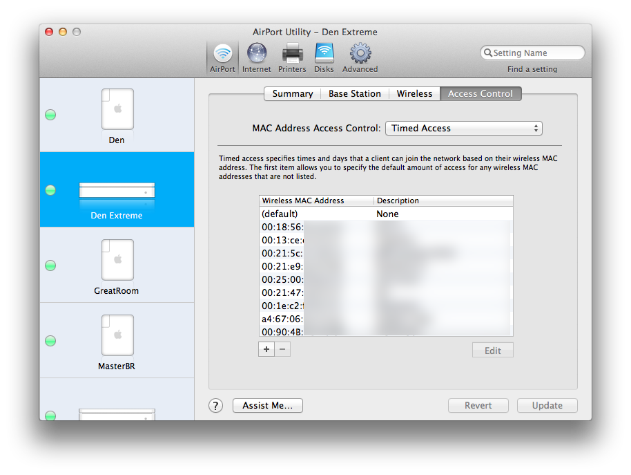
The first difference between my solution and the blog post referenced above is the setting of Mac Address Access Control to Timed Access:

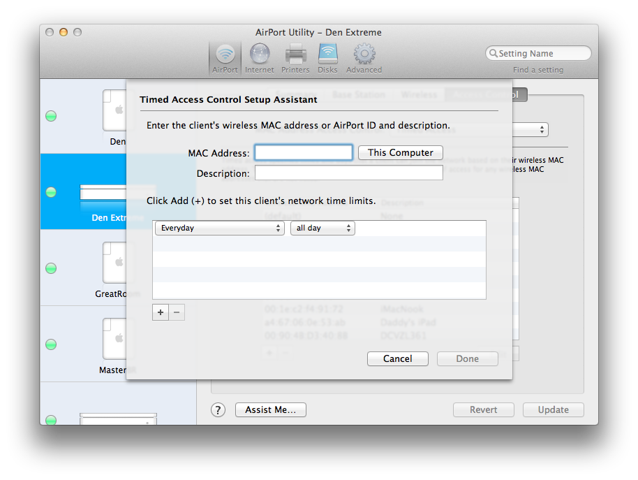
Adding the Airport ID of the AEBS to the access control list (ACL) to allow 24×7 access (add Airport ID in MAC Address field below) was necessary:

It was also necessary to add the MAC address of the Ethernet port of the device being connected to the AEBS to the access control list.  This would allow the access point to reply to the DHCP requests from the device connected to the AEBS via Cat-5.  If you have assigned a static IP to this device, then adding this MAC to the ACL is not necessary.

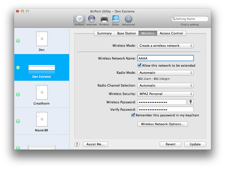
I added the access control entries to the Den Extreme base station which I knew would be closet to the AEBS, I also ensured the Allow this network to be extended box was checked for the same Extreme on the Wireless tab:

I thought that this would be it and I would have my connection. As it turns out I was wrong.

Almost There

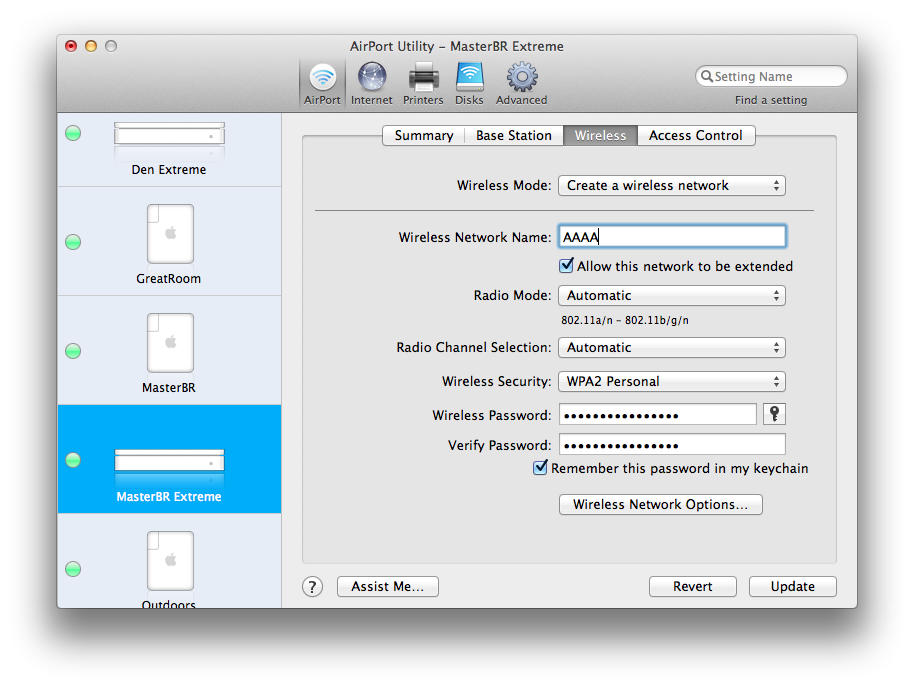
I checked the AEBS to make sure that it was in fact a client of the Den Extreme base station, and it was. I then rechecked the access control list in the Den Extreme and it still contained the AEBS AirPort ID–that configuration was saved properly. It then occurred to me that I should check the access control lists on the TC and the other Extreme base station. As expected, they both had inherited the changes to the access control list allowing the AEBS access. What was different is that the Allow this network to be extended box was not checked on these other devices. So I checked the box on the second Extreme base station:

and on the Time Capsule:

After saving these configurations and allowing all the base stations to restart I finally had my solution.

In Short

The solution consists of:

  • Starting with the blog post as referenced above
  • Adding the AEBS AirPort ID to the Access Control List (ACL) for the wireless network, as well as the MAC address of the connected device (if not assigned a static IP)
  • Ensuring Allow this network to be extended is checked on all wireless base stations serving the wireless network
Categories
Embedded Networking

Trials and Tribulations of using Embedded TCP

I was recently called in for a consult on a program that was having trouble with their 802.11 link.

The team working on this program had created a system using a number of embedded micros which were to communicate via Ethernet on an embedded LAN. In my experience, network communications on an embedded LAN normally run fairly smoothly because you are in total control of the environment. You can design the system based on the bandwidth required and put in Ethernet controllers which support those bandwidth requirements.  You can control who talks when and totally avoid the possibility of collisions occurring.

As it turns out that the system created was so complex that the team was unable to get all these micros communicating effectively in a timely fashion while at the same time doing all the number crunching that needed to be done.  The decision was made to backtrack a bit and prototype some of the systems on PCs instead of micros.

This course of action lead to the use of the 802.11 link; what was to be an embedded LAN now became partially embedded and partially a wireless LAN connecting the PCs.  Wireless LANs have their own issues–link saturation, SNR, etc.–some of which I’d had to deal with in the past on prior projects. This is what prompted the request for my help; the team was getting very little data across their wireless link and couldn’t understand why.

After asking a few questions I discovered a couple things:

  1. they were using TCP/IP for their network connections, and
  2. the software engineers had never done network programming

These two factors, combined with the wireless LAN, made for the perfect storm.

The low bandwidth that the team was seeing was due to the fact that TCP uses an exponential backoff mechanism when attempting to guarantee packet delivery. What caused the backoff to occur in the first place were some easily fixed wireless hardware issues.

What compounded the issue was the fact the the socket code on the micros was sending data without regard for the health and status of the socket.  In essence, they were also overflowing their transmit buffers.  This was because the engineers writing the code didn’t know any better.

After shaking my head and rolling my eyes at the state of affairs, the issues were fixed by resolving the wireless hardware issues and instructing the engineers in the use of the select() function to control the flow of data on the socket and monitor its health.

The system now works and the team recently executed a very successful demonstration, but I still have an issue with the fact they are using TCP in the system. Since you control the network and all the traffic on an embedded LAN, TCP is not required.  TCP is designed for traveling long distances through hardware of unknown origin and state; it is not required in a highly controlled embedded environment. In this environment, for this program, UDP is more than sufficient. Here’s why:

  1. The system is tolerant to a small percentage of data loss.
  2. UDP packets are checksummed at higher level–Ethernet CRC checksum and IP Header checksum.  If you get a packet then you are pretty much guaranteed the data is correct.
  3. The 100Mbps links on the system above provides more than ten times the bandwidth required–it had 5 nodes each transmitting less than 1 Mbps.  Staggering their communications to avoid collisions is a simple matter.
  4. Fragmentation can be eliminated by sending data in blocks no larger than a single MSU.
  5. UDP simplifies.  Creating and maintaining connections of a TCP socket can be time consuming and distracting, adding a lot of code with no added value.
  6. UDP datagram loss on a closed embedded LAN is negligible.

Item 5 and 6 above were particularly costly in this instance, many hours were spent maintaining connection oriented code when the occasional loss of data would not have had a negative impact on the system results.  In this case, even including the wireless LAN, iperf tests showed less than 0.02% datagram loss at the bandwidths this system was running.

Just as everything else posted here, this is one engineer’s opinion.  I hope by stating it, I can help you avoid some of the travails I’ve experienced.

Categories
Networking

The End of Endianness

I very much dislike dealing with cross-platform endian issues.   When it comes to defining structures with bitfields–it can sometimes become a pain to order all the fields correctly depending on the platform one is using.

Another headache is dealing with host byte ordering and network traffic on Intel platforms–all that byte swapping!!!

Anyway, I’ve been using some simple functions that allow me to parse the message on the fly while it is still in network byte order with no need for byte swapping or structures with bitfields.

The great thing about this code is that it is cross-platform; absolutely no endian issues to deal with.  The price paid for this portability is execution speed–this code will likely be slower when parsing many fields out of a large message.  But if you only need one or two fields from a large message, then this code will actually be faster than byte swapping the entire message.

Below you will find the bitfield extract code header file, then give a small sample program which uses it, and its corresponding output.

Here’s the bitfieldextract.h header file:

#ifndef __BITFIELDEXTRACT_H__
#define __BITFIELDEXTRACT_H__

#if !defined(WIN32)
typedef unsigned long UINT32;
typedef unsigned short UINT16;
typedef unsigned char UCHAR;
typedef unsigned char *PUCHAR;
typedef char *PCHAR;
#else
#include 
#endif

/*
//
// bfx -- bit field extract
//
// extract up to a 32-bit value at any bit
// offset in a byte array
//
*/
inline UINT32 bfx(
  const PUCHAR cptr,
  UINT32 bit_offset,
  UINT32 bit_len)
{
  /*
  // Portable bit field extract code
  */

  UINT32 byte_off    = ( bit_offset >> 3 );
  UINT32 left_shift  = bit_offset - ( byte_off << 3 );
  UINT32 bytes       = ( left_shift + bit_len + 7 ) >> 3;
  UINT32 right_shift = ( bytes << 3 ) - ( bit_len + left_shift );
  UINT8  cval;
  UINT32 val, i;

  /* grab first byte  and apply shift */
  cval = cptr[byte_off] << left_shift;
  val  = cval;
  bytes -= 1;

  if (bytes) {
    /* shift back high order byte */
    val >>= left_shift;

    /* reset left shift since we did it already */
    left_shift = 0;
  }

  for (i=1;i> right_shift );

    /* reset right shift since we did it already */
    right_shift = 0;
  }

  return val >> ( left_shift + right_shift );
}

/*
// bfxi -- bit field extract and increment
//
// extract up to a 32-bit value at any bit
// offset in a byte array and auto-increment
// the bit offset by the number of bits read
*/
inline UINT32 bfxi(
  const PUCHAR cptr,
  UINT32 &bit_offset,
  UINT32 bit_len)
{
  UINT32 val = bfx(cptr, bit_offset, bit_len);

  bit_offset += bit_len;

  return val;
}

#endif

Here’s a small program that uses it:

#include 
#include "bitfieldextract.h"

using namespace std;

int main(int argc, char* argv[])
{
  UCHAR x[6] = { 0x12, 0x34, 0x56, 0x78, 0x9a, 0xbc };
  unsigned int ofs = 0;
  int i;

  cout << "Binary representation of buffer "
    << "[ 0x12 0x34 0x56 0x78 0x9a 0xbc ]:"
    << endl << endl << "  ";

  for (i=0;i<48;i++)
    cout << bfxi(x, ofs, 1);
  cout << endl << endl; 

  cout << "Each 4-bit nibble:"
    << endl << endl << "  ";

  ofs = 0;
  for (i=0;i<12;i++)
    printf("0x%1x ", bfxi(x, ofs, 4));
  cout << endl << endl; 

  ofs = 2;
  cout << " 2 bits at " << ofs << " = ";
  cout << bfxi( x, ofs, 2 ) << endl;
  cout << " 4 bits at " << ofs << " = ";
  cout << bfxi( x, ofs, 4 ) << endl;
  cout << " 6 bits at " << ofs << " = ";
  cout << bfxi( x, ofs, 6 ) << endl;
  cout << " 8 bits at " << ofs << " = ";
  cout << bfxi( x, ofs, 8 ) << endl;
  cout << "10 bits at " << ofs << " = ";
  cout << bfxi( x, ofs, 10) << endl;

  for (i=4;i<=8;i++) {
    ofs = i;
    cout << "32 bits at " << ofs << " = ";
    printf("0x%08x\n", bfxi( x, ofs, 32));
  }
  ofs = 16;
  cout << "32 bits at " << ofs << " = "; 
  printf("0x%08x\n", bfxi( x, ofs, 32));

  return 0;

}

And the associated output:

Binary representation of buffer [ 0x12 0x34 0x56 0x78 0x9a 0xbc ]:

  000100100011010001010110011110001001101010111100

Each 4-bit nibble:

  0x1 0x2 0x3 0x4 0x5 0x6 0x7 0x8 0x9 0xa 0xb 0xc

 2 bits at 2 = 1
 4 bits at 4 = 2
 6 bits at 8 = 13
 8 bits at 14 = 21
10 bits at 22 = 632
32 bits at 4 = 0x23456789
32 bits at 5 = 0x468acf13
32 bits at 6 = 0x8d159e26
32 bits at 7 = 0x1a2b3c4d
32 bits at 8 = 0x3456789a
32 bits at 16 = 0x56789abc